Asus EEE901 display backlight repair
I have two displays without working backlight. I have bought 3rd, used LVDS cable from one of mine displays
and backlight wasn't working on this one too. I looks like problem on the motherboard, but display from
Asus EEE1000H worked perfectly there.
There was 4.94V on EEE901 backlight (back of the display) and 8.58V on EEE1000H's backlight. It looked like
LED and not CCFL, so I have tried to find a datasheet.
A089SW01-V0
Yes, it is LED backlight with 3 LEDs in series, maximal voltage on LEDs 10V and maximal current to the
convertor 400mA (but on 4.5-5.5V, not on 10V!), therefore I guess, that maximal current to the display
will be around 200mA.
I have tried to push a few miliamps to it and it worked properly. I'm not sure what was wrong, it looks
like design failure in power convertor on both displays, but it doesn't explain the 3rd display. Both
cables may be wrong, but that doesn't explain why there was 5V on power convertor's output. Everything
in the display is 3.3V, just supply for backlight is 5V, therefore wires for this supply seems to be o.k.
Laptop works perfectly with external power source for backlight. It will need some power convertor for it.
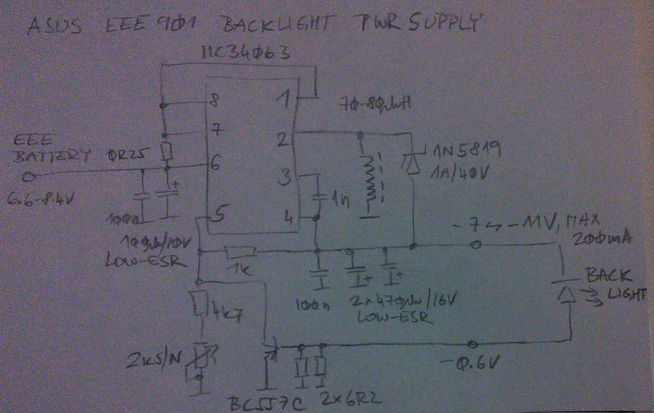
Power convertor
The display starts to be backlighted on 7.6V
(readable in darkness) and the maximal current 200mA has been reached on 9.66V, while battery consists
of two LiION cells with voltage range 6.6V to 8.4V.
The highest voltage needed for display is higher than the voltage of battery, so it's obvious, that there
must be some power convertor. Worse - the ranges are overlapping, which rules out simple step-up. What
are the options? SEPIC, Cuk, buck-boost, gamma, step-up with additional linear down convertor (not very
effective) and invertor. The first four convertors are pretty complicated with more coils or more switchers.
Backlight's input is not connected to any voltage in the laptop, so I felt free to use invertor.
The efficiency is poor - it's using bipolar switch and schottky diode for rectification (synchronous one
would be better). To be honest - the efficiency is even poorer than datasheet suggests, because the resistor
between base of the BC557C transistor and ground eats additional 0.6V at full current. But it's pretty simple.
If the voltage on the 3.1 ohm resistor (two 6.2 ohm in parallel) reach 0.6V, it is going to open the
BC557C transistor, which lower the output voltage of the power convertor. It isn't very accurate, because
the maximal current varies with voltage a bit, but it's good enough for this usage. Use op amp instead of
this if you want lower voltage drop and better regulation.
It worked properly without two 100nF capacitors but it's better to not send lots of current peaks to the
laptop. Capacitors are from dead PC motherboard, coil too, but it has been rewinded.